NORFOLK NAVY YARD
DRY DOCK 1
Marcus W. Robbins, Historian & Archivist
Copyright. All rights reserved.
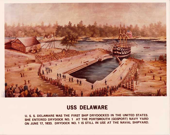
USS DELAWARE 1st Docking in North America June 17, 1833

|
|
NORFOLK NAVY YARD
DRY DOCK 1
Marcus W. Robbins, Historian & Archivist
Copyright. All rights reserved.
USS DELAWARE 1st Docking in North America June 17, 1833
|
|
|
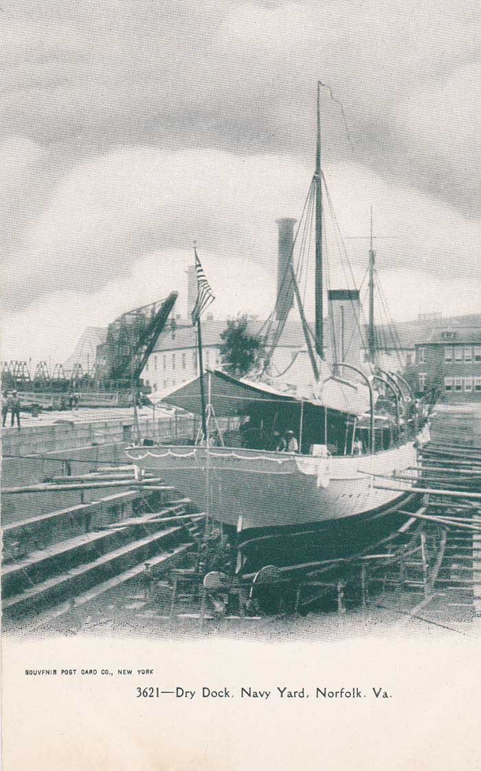
Dry Dock 1 circa 1903
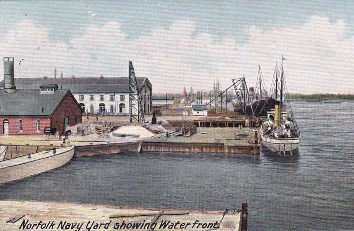
Dry Dock 1 & 2 Waterfront circa 1904
Dry Dock 1 circa 1905
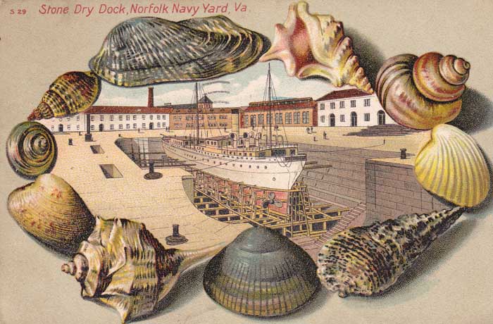
Dry Dock 1 shells circa 1905
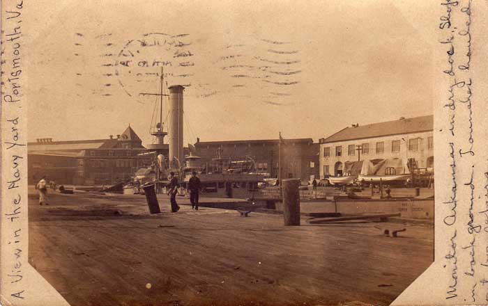
Dry Dock 1 Monitor Arkansas April 15, 1908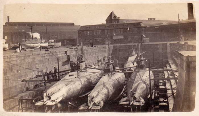
Dry Dock 1 Subs 9, 10, 11 & 12 circa 1910
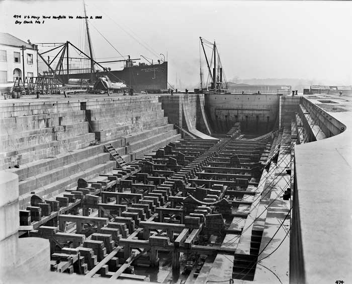
Dry Dock 1 March 2, 1906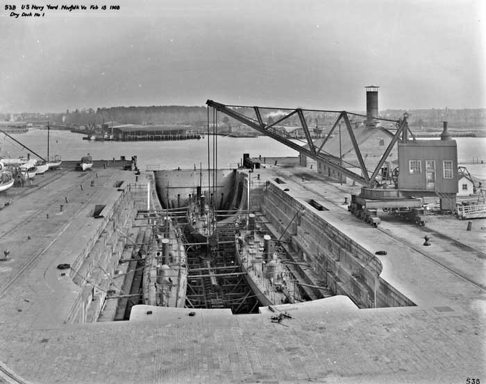
Dry Dock 1 Crane February 18, 1908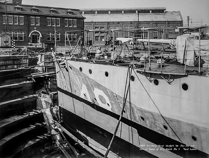
Dry Dock 1 November 28, 1916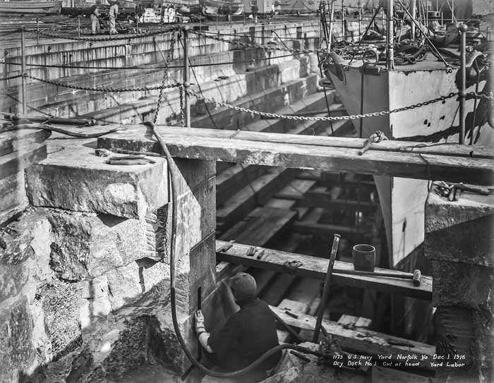
Dry Dock 1 December 1, 1916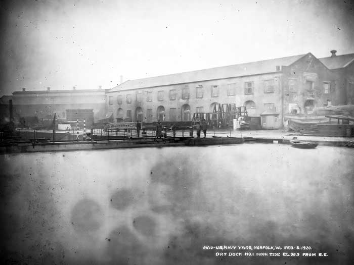
Dry Dock 1 February 5, 1920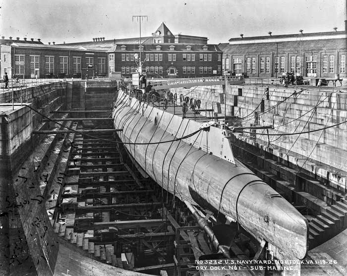
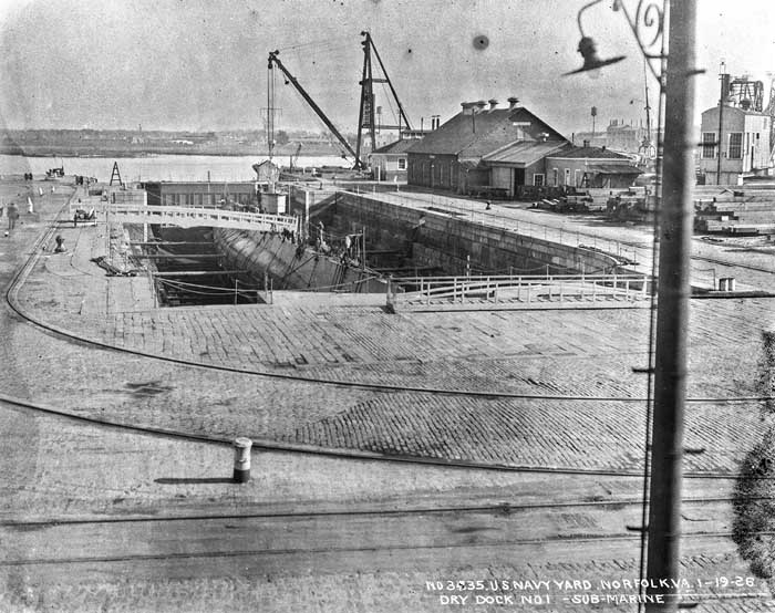
Dry Dock 1 Submarine January 19, 1926
Dry Dock 1 Submarine January 19, 1926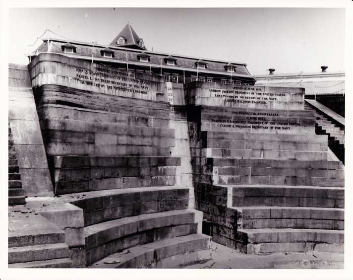
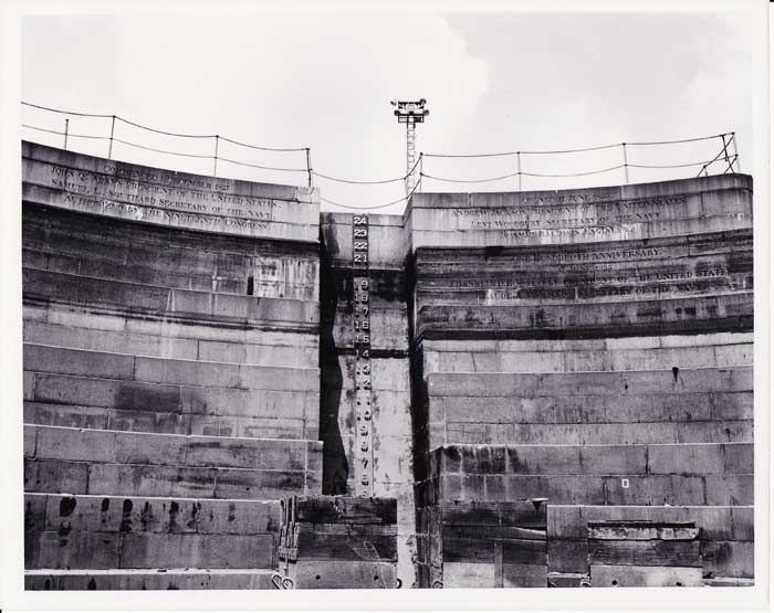
Dry Dock 1 Headwall circa 1933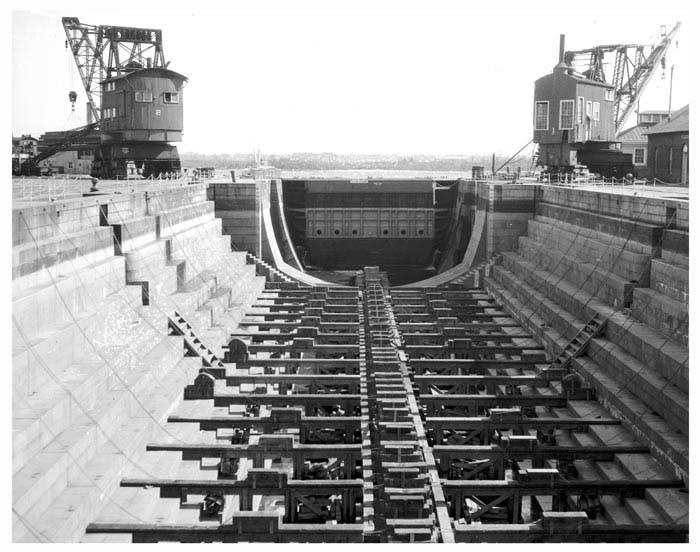
Dry Dock 1 Looking East circa 1940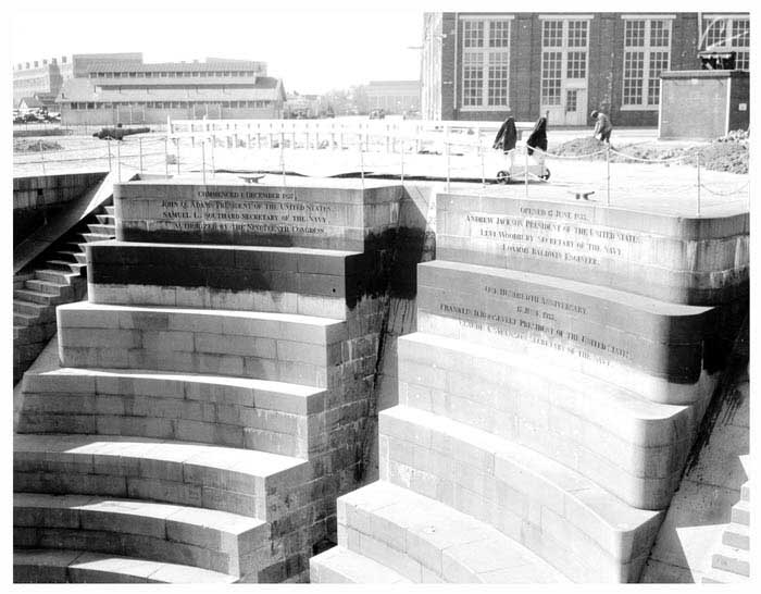
Dry Dock 1 Looking West circa 1940
Dry Dock 1 Headwall circa 1960
EXCERPTS from:
History of the United States Navy-Yard at Gosport, Virginia,
(Near Norfolk)By Edward P. Lull, A. M.,
Commander, United States Navy
For the Bureau of Yards and Docks, Navy DepartmentRear-Admiral C. R. P. Rodgers, U. S. N., Chief of Bureau
Washington: Government Printing Office.
CONSTRUCTION OF THE DRY-DOCK
The work upon the dry-dock was commenced in November, 1827. Colonel Baldwin was appointed engineer in charge of the construction of this as well as of that authorized at Boston ; and Capt. W. P. S. Sanger was appointed resident engineer at Gosport. Captain Sanger continued the immediate charge of the work under Colonel Baldwin until its completion, and to him the writer is indebted for the most of the following information on the subject, a part of which, derived from the same source, was published some years since by Mr. Charles B. Stuart.
The northernmost of the three sites selected for docks in the plan was chosen for the one about to be built. As will be seen by reference to the plan, the site as laid down projected about 130 feet outside of the shore-line or into about 10 feet of water. The average surface of the ground inside the shore-line was 6 feet above high-water mark.COFFER-DAM
A strong water-tight coffer-dam was built as a preliminary step to beginning the excavation ; this consisted of two rows of piles 12.5 feet apart, directly in front of the dock, and 8 feet apart at the sides. Each row consisted first of ribbon-piles 14 inches square and 45 feet long, driven 8 feet apart, to which were bolted ribbons of 12 by 14 inch yellow-pine timber, one at the. head of the piles, one 6-1/2 feet, and one 10-1/2 feet lower; inside of the ribbons, i. e., toward the interior of the dam, were driven sheet-piles 13 inches square, and tongued and grooved. The rows were then secured to each other by tie-beams laid across and secured to the heads of the ribbon-piles; and by 2-inch iron bolts through the lower ribbons, one between each two of the ribbon-piles. The intervening space between the rows was then filled with clay from the excavation. The dam was found to be perfectly tight and secure, and never gave any trouble while in use.COB-WHARF
Joining on to the coffer-dam, on either side, was constructed a cob-wharf; that to the southward extended only some 40 yards when it turned in to the shore; but that to the northward extending along the proposed line of the quay-wall to the entrance of the proposed timber-dock, where it joined a crib-work built along the line designated for the south wall of the latter.SOIL AND EXCAVATION
The excavation for the dock was now pushed steadily forward, and the earth removed was used to fill in from the shore-line to the cob-wharf above mentioned, and to level other portions of the yard. The [33] soil for a depth of from 5 to 12 feet was a yellow sand; next a stratum of fine compact blue clay, with here and there upon its upper surface irregular strata of blue sand, and of shells mixed with clay. The blue clay extended at the entrance of the dock about 30 feet below the bottom of the pit, and at the head diminished to 15 feet, where a bed of gravel was reached, so hard that an auger would not penetrate it. The pit was, when the excavation was finished, 40 feet deep, 340 feet long, and 100 feet wide at the bottom; the sides sloping so as to make it about 60 feet wider, and as much longer at the top. A chalybeate spring was met in the excavation, the flow of which was so strong as to force the water through the pores, of the piles which were driven. An auger-hole being bored in the head of a pile, the water would flow out of it freely. The summit of this spring was some six feet below the level of the low-water mark.FOUNDATION OR BEARING PILES
The pit having been prepared, foundation or bearing piles were driven in rows 3 feet apart from center to center, but somewhat closer along the central line of the pit. These piles were about 30 feet long at the entrance, and gradually diminished in length to 15 feet at the head, being driven down to the stratum of gravel above referred to, into which it was impossible to make them enter more than a few inches. A row of sheet-piles was next driven across the head and along either side of the pit, a row across the front entrance, one under where the grooves for the floating-gate were to be, one under the turning-posts of the gates, and one under the gallery. These rows of sheet-piles act both as stop-waters and as additional supports to the foundation.FOUNDATION
The heads of the bearing-piles were cut off level, and upon them were placed, transversely with the axis off the dock, yellow-pine beams 12 inches thick either way, and secured to the piles by treenails. The spaces between the beams and to the level of their upper surfaces were then filled with broken stone, after which a close floor of 4-inch yellow-pine plank was laid, and upon this and directly over .the lower was placed a second course of timber 12 inches thick by 16, laid edgewise; the intermediate spaces between these were filled with brick laid in cement, after this another floor similar to the first was put down.MASONRY
All the dimension stone of this dock is of granite from different Massachusetts quarries, and nearly all of it was dressed in the quarries from the plans, and so well was this work done that it is estimated that not $100 were spent in altering stone. The rubble-backing to the side-walls was obtained principally from the quarries at Port Deposit, Md. A small portion, however, came from the Falls of the James River, near Richmond.
[34] The chamber of the dock, or the portion ordinarily used for docking ships, is 253 feet long and 85-1/2 feet wide at the coping. The extreme length of the dock, which can be made available by placing the floating-gate outside the entrance and not using the turning-gates, is 320 feet. The United States ship Severn, measuring 324 feet over all, was recently docked by blocking up to raise her above the miter-sills. The floor of the chamber is 227 feet long and 30 feet wide. The increase in the width of the chamber from the floor to the coping is produced by offsets in the side-walls forming the altars. The side-walls are 35 feet thick at the bottom and but 7 at the coping. The floor is laid in two courses of cut granite in the form of an inverted arch, to resist the upward pressure of the water; the lower course is tapering in form, 1 foot thick at the entrance of the chamber and 2 feet 3 inches at the head, thus giving a rise of 1 foot 3 inches; the second course is of uniform thickness, i. e., 3 feet.
The lowest two altars have a rise of 15 inches each, the floor rising to the level of the lowest altar at the head of the chamber; the next three have a rise of 1 foot each. These five altars are laid so as to form a continuation of the inverted arch; the next three rise 3 feet each; the next three, 4 feet 4-1/2 inches each; when a further rise of 4 feet 4-1/2 inches brings us to the coping. The width of the altars from the lowest up are as follows: The first, 3 feet; the next three, 2 feet each; the next, 4 feet; the next two, 2-1/2 feet each; the next, 4 feet; and the upper three, 2 feet each. The head of the chamber is semicircular. There are five timber-slips in the head of the dock, with landings upon the broad altars. There are six flights of stone stairs in the chamber for the use of workmen, three on each side, viz, one at the head; one at the center; and one at the entrance. At the entrance of the chamber is the gallery, which is the lowest part of the floor, and from which the water passes through gates into the discharging-culverts. Next, outside the gallery, is the great inverted arch; the miter-sills against which the turning-gates rest when closed, abut against this arch. Vertical recesses in the side-walls receive the turning-gates when open. Outside of these recesses, at the entrance of the dock, is another inverted arch, a groove in which, and continued up the side-walls, receives the floating-gate. The floating-gate may, however, as has been mentioned above, be placed against shoulders in the face of the entrance, thus increasing the capacity of the dock.CULVERTS
On either side of the dock a culvert 4 feet high and 2-1/2 feet wide in the opening, and provided with a bronze gate, leads from the gallery to the reservoir across the head of the dock; the culverts are built of hard brick laid in cement, with straight side-walls and semicircular tops and bottoms; the thickness of the walls is 14 inches.
The reservoir is 12 feet high and 7 feet wide, built with straight side- [35] walls of cut granite, a semicircular top of brick 14 inches thick, and a brick inverted arch at the bottom of the same thickness.
From the south end of the reservoir, (where a well is situated, reaching to the surface,) a tunnel, with cross-section elliptical in form, 4 feet high and 2 feet 9 inches wide in the opening and about 190 feet long, leads to the pump-well. From the pump-well a discharge-culvert about 150 feet long leads into the creek at the southwest corner of the yard; it is about 4 feet square at the mouth, and supplied with a composition gate.
Water is admitted to the dock through filling-culverts, one on either side, 14 feet 9 inches below the coping, and leading inside of the turning-gates; these culverts also are supplied with bronze gates.PUMP-WELLS AND ENGINE-HOUSE
There are two pump-wells 15 feet 9 inches in diameter each, and connected together; they are built of brick; the bottoms are inverted arches, 2 feet thick; the side-walls are 2-1/2 feet thick, with four projecting courses of cut stone at proper intervals to support the pump-frames. On the tops of the walls are stone copings 1 foot deep and 18 inches wide.
There are four lift-pumps in each well, each 30 inches in diameter and of 3 feet stroke, made of cast iron, lined with composition staves and supplied with composition boxes and valves. The pumps are driven by pinion-wheels fitted on either end of the engine-shaft, working in cog wheels on the shafts of the pumps.
The engine-house was a two-story brick building, 200 feet long by 50 feet wide; but 50 feet of the lower story was used for the lifting-engines; the rest of the building was at first occupied as a saw-mill and as a machine-shop. The whole is now used as a machine-shop.GATES
The turning-gates are constructed of timber and composition, and covered with copper. Each gate is 36 feet wide and 30 feet 8 inches in height. The turn-posts are fitted with composition saucers in the lower ends, which rest upon composition pintles fixed in the masonry; the tops of the posts are secured in place by straps keyed to anchors laid in the coping. Each gate is supplied with two composition rollers, and cast-iron tracks are laid upon the floor for these to travel upon.FLOATING GATE
The floating-gate, or caisson, is built of white-oak timber and yellow pine plank, copper-fastened. It is 60 feet long, 30 feet high, and 16 feet wide amidships. The stems and keel are each 2 feet thick, and project 14 inches into the grooves in the walls and arches. There is a fore-and-aft bulk-head from stem to stern and from deck to keelson, composed [35] of solid timber, and 2 feet thick. Three courses of tie-beams from this bulk-head to the sides resist the pressure of the water Four copper ship's pumps on each side, and worked by brakes on deck, are used for pumping out the water when it is desired to lift the gate out of the grooves.
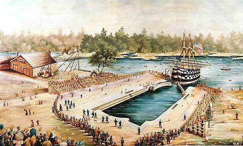
On the 17th of June, 1833, the anniversary of the battle of Bunker Hill, the dock was opened for the reception of the line-of-battle ship Delaware, the first liner built at Gosport, and the first national ship ever docked in a dry-dock belonging to the United States.
Large numbers of ladies and gentlemen were present to witness the opening ceremonies, which were made as imposing as possible, the occasion being one of great rejoicing as well to the citizens of Norfolk and Portsmouth as to the whole Navy.
The line-of-battle ship North Carolina was soon afterward admitted to the dock.
The dry-dock was turned over to the commandant of the navy-yard complete on the 15th of March, 1834. The total cost of the work was $974,356.65. The following is a tabulated statement of expenditures up to October 1,1833, as published in the report of the Secretary of the Navy for that year:ITEMS AMOUNTS
Offices, shop, and stables $22,119.75
Tools, lighters, driving-machines, &c 41,420.44
Pine-timber, plank, mails, iron, &c 17,794.34
Surveys and plans of navy-yards *3,360.26
Coffer-dam 23,532.84
Pier wharves 10,972.50
Cob-wharves *14,022.59
Excavation 58,572.33
Foundation 64,097.46
Drainage, (temporary) 33,803.46
Masonry of dock 450,789.62
Banking up 11,432.72
Wells and tunnel 13,762.02
Engine-house 33,901.97
Engine and pumps 27,945.22
Turning-gates 22,588.43
Floating-gate 24,121.54
Removal of coffer-dam 8,134.81
Miscellaneous 35,010.55
Superintendence 31,256.88
TOTAL 943,645.73* These items not belonging properly to the dock, their cost should not be included. The engine-house was used for other purposes also, so that part only of its cost should be charged to the dock.
DRY DOCK CONSTRUCTION PLANS March 3, 1827 (pdf file)
DRY DOCK 1 NOMINATION FORM for National Register of Historic Places February 26, 1970 (pdf file)